[Main body of content prompted and curated by Jason Head]
– mapping (via config or rules in Node-RED)
– storage (via REST API or MQTT into MES – here the Nexeed Shift Book module)
Reference: Shift Book API documentation:
https://learn.bosch-nexeed.com/en/shopfloor_management_administration/api/api.html
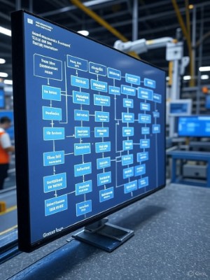
graph TD
    A[Start Automate Loss Codes] --> B[Read PLC Signals<br>- Signal for stop<br>- Signal for alarm]

    B --> C{Map Signals to Loss Codes}
    C -->|JSON Config| D[Create JSON File<br>- Map signals to loss codes<br>- Load in Node-RED]
    C -->|Node-RED Rules| E[Add Function Node<br>- Match signal to loss code<br>- Set payload<br>- machine id<br>- loss code<br>- timestamp]

    D --> F[Track State Changes<br>- Trigger Node<br>- Detects start end<br>- Calculates duration]
    E --> F

    F --> G{Store in MES e.g. Nexeed Shift Book}

    G -->|MQTT| H[Publish MQTT<br>- Broker address port<br>- Topic for downtime<br>- Payload<br>- machine id<br>- loss code<br>- start time<br>- duration]

    G -->|REST API| I[Send POST API<br>- to MES e.g. Nexeed Shift Book<br>- Payload<br>- machine id<br>- loss code<br>- start time<br>- duration<br>- Add API key in headers]

    H --> J[Check MES UI<br>- e.g. Nexeed Shift Book]
    I --> J

    J --> K[End Downtime Logged]
1. Read PLC Signals
What: Connect to PLC to read signals (e.g., stop bit, alarm).
How:
- Add Input Node (e.g., OPC UA): Set PLC IP, endpoint; poll signals every 1s.
- Output:
msg.payload = { address, value }. - Test: Check Node-RED debug tab.
Trade-offs: OPC UA is vendor-neutral but needs certificate setup; protocol-specific nodes may be simpler but less flexible.
2. Map Signals to Loss Codes
What: Map PLC signals to MES loss codes (e.g., stop to downtime category). Two options:
Option 1: JSON Config
How:
- Create
mappings.json:[{signal: "<address>", loss_code: "<category>"}]. - Add File Node: Load
mappings.json. - Add Change Node: Set
global.mappingstomsg.payload. - Use in Function Node (see step 3).
- Update: Edit JSON for new signals.
Trade-offs: Easy updates via file, ideal for scaling, but requires initial JSON setup.
Option 2: Node-RED Rules
How:
- Add Dashboard Node (
node-red-dashboard): Create UI to input signal-to-loss-code mappings. - Store mappings in
global.mappingsvia Change Node. - Add Function Node: Read
global.mappings, match signal, set payload (machine_id, loss_code, timestamp). - Test: Inject signal, check debug tab.
- Update: Add/edit mappings via dashboard UI.
3. Track State Changes
What: Detect signal changes (e.g., true to false) to log start/end and duration.
How:
- Add Trigger Node: Send
msg.payloadon start, wait for opposite state, addduration. - Test: Inject signals, verify duration in debug tab.
4. Store in MES
What: Send downtime events to MES. Two options:
Option 1: MQTT
How:
- Get MES MQTT details (e.g., broker, topic, credentials).
- Add MQTT Out Node: Set broker, topic (e.g.,
<mes_path>/<machine_id>/downtime), QoS 1, payloadmsg.payload. - Test: Use MQTT client to verify payload.
Tools: MQTT client
Trade-offs: Lightweight, real-time, minimal auth, but requires MQTT support.
Option 2: REST API
How:
- Get MES API details (e.g., endpoint, API key).
- Add HTTP Request Node: POST to endpoint, set headers with API key, payload
msg.payload. - Test: Use API client for 200 OK response.
Tools: API client
Trade-offs: Robust for complex payloads, guaranteed delivery, but needs auth setup, may face rate limits.
5. Verify in MES UI
What: Check MES UI for logged events.
How:
- Log into MES UI, filter by machine/date.
- Verify loss code, timestamp, duration.
Trade-offs: Manual check ensures accuracy but takes time; automated checks are faster but need scripting.
Summary
Confirm MES details via provider portal. Secure with TLS. Test one signal, then scale. Align loss codes with OEE standards.
Step-by-Step Node-RED Implementation with Nodes
1. Read PLC Signals
What: Connect to PLC to read signals (e.g., stop bit, alarm).
Nodes to Use:
- Input Node (e.g., OPC UA Client Node): Use a node like
node-red-contrib-opcua(from “opcua” palette) to read PLC signals. Configure with PLC IP, endpoint, signal addresses (e.g., stop bit, alarm). Set poll interval to 1 second. Output:msg.payload = { address: "<signal>", value: true }. - Debug Node: Connect after Input Node (from “common” palette) to verify signal data in debug tab.
Process: Input Node reads PLC signals, outputting msg.payload with address and value. Debug Node confirms data.
2. Map Signals to Loss Codes
What: Map PLC signals to MES loss codes (e.g., stop to downtime category). Two options: JSON Config or Node-RED Rules.
JSON Config
Nodes to Use:
- Inject Node: Triggers JSON file loading (from “common” palette). Set to run once on flow start or periodically (e.g., hourly).
- File In Node: Reads
mappings.json(from “storage” palette). Configure: Filename to~/.node-red/mappings.json. Output: Parsed JSON object (msg.payloadas array, e.g.,[{signal: "<address>", loss_code: "<category>"}]). - Change Node: Stores mappings (from “function” palette). Configure: Set
global.mappingstomsg.payload(e.g.,global.set("mappings", msg.payload)). - Function Node: Processes mappings (from “function” palette, used in step 3). Reads
global.mappings(detailed in step 3). - Debug Node: Connect after Change Node to verify
global.mappings.
Process: Inject Node triggers File In Node to load mappings.json. Change Node stores JSON array in global.mappings. Function Node (step 3) maps signals. Update by editing mappings.json and re-triggering Inject Node.
Node-RED Rules
Nodes to Use:
- Dashboard Nodes (node-red-dashboard): Use
ui_formandui_button(from “dashboard” palette) for web UI to enter signal-to-loss-code mappings. Configureui_formwith fields for signal address and loss code; output:msg.payload = {signal: "<address>", loss_code: "<category>"}. Configureui_buttonto trigger adding mappings. - Change Node: Stores mappings (from “function” palette). Configure: Append
msg.payloadtoglobal.mappings(e.g.,global.set("mappings", [...global.get("mappings") || [], msg.payload])). - Function Node: Processes mappings (from “function” palette, used in step 3). Reads
global.mappings(detailed in step 3). - Debug Node: Connect after Change Node to verify
global.mappingsupdates.
Process: Dashboard UI (ui_form, ui_button) sends mappings as msg.payload. Change Node appends to global.mappings. Function Node (step 3) maps signals. Update via UI without editing flows.
3. Track State Changes
What: Detect signal changes (e.g., true to false) to log start/end and duration.
Nodes to Use:
- Function Node: Processes
global.mappings. Configure:
Input:let mappings = global.get('mappings') || []; let match = mappings.find(m => m.signal === msg.address); if (match && msg.payload.value) { msg.payload = { machine_id: "<machine_id>", // Set via env variable or config loss_code: match.loss_code, start_time: new Date().toISOString() }; return msg; } return null;msg.payload = { address: "<signal>", value: true }from Input Node. Output:msg.payload = { machine_id, loss_code, start_time }. - Trigger Node: Tracks state changes (from “function” palette). Configure: Send
msg.payloadon signal start (e.g., true). Wait for opposite state (e.g.,msg.payload.value = false) or timeout. Output: Addduration(in minutes) tomsg.payload(e.g.,{machine_id, loss_code, start_time, duration}). - Debug Node: Connect after Trigger Node to verify output.
Process: Function Node maps PLC signals to loss codes using global.mappings. Trigger Node detects start/end, adds duration. Debug Node confirms output.
4. Store in MES
What: Send downtime events to MES. Two options: MQTT or REST API.
MQTT
Nodes to Use:
- MQTT Out Node: Publishes to MES broker (from “network” palette). Configure: Broker to
<broker>:1883(from MES provider). Topic to<mes_path>/<machine_id>/downtime. QoS: 1. Payload:msg.payload(from Trigger Node). - Debug Node: Connect after MQTT Out Node to verify sent data.
Process: MQTT Out Node sends msg.payload (e.g., {machine_id, loss_code, start_time, duration}) to MES topic. Test with MQTT client.
REST API
Nodes to Use:
- HTTP Request Node: Sends POST to MES (from “network” palette). Configure: Method: POST. URL:
<mes_api>/events(from MES provider). Headers:{"Authorization": "Bearer YOUR_API_KEY"}. Payload:msg.payload(from Trigger Node). - Debug Node: Connect after HTTP Request Node to verify response (e.g., 200 OK).
Process: HTTP Request Node sends msg.payload to MES API. Test with API client.
5. Verify in MES UI
What: Check MES UI for logged events.
Nodes to Use:
- None in Node-RED; manual verification in MES UI.
Process: Log into MES UI, filter by machine/date, verify loss code, timestamp, duration. Screenshot for records.
6. Maintenance
What: Update mappings, monitor system.
Nodes to Use:
- For JSON Config: Edit
mappings.json, trigger Inject Node → File In Node → Change Node to reload. - For Node-RED Rules: Use Dashboard Nodes (
ui_form,ui_button) to updateglobal.mappings. - Debug Node: Monitor
msg.payloadorglobal.mappings. - Dashboard Nodes: Use
ui_textorui_table(fromnode-red-dashboard) to display mappings or logs.
Process: Update mappings via JSON file or dashboard UI. Monitor via debug tab or dashboard UI.
Summary of Nodes
- Read PLC Signals: Input Node (e.g., OPC UA), Debug Node.
- Map Signals to Loss Codes:
- JSON: Inject Node, File In Node, Change Node, Function Node (used in step 3), Debug Node.
- Rules: Dashboard Nodes (
ui_form,ui_button), Change Node, Function Node (used in step 3), Debug Node.
- Track State Changes: Function Node, Trigger Node, Debug Node.
- Store in MES:
- MQTT: MQTT Out Node, Debug Node.
- API: HTTP Request Node, Debug Node.
- Verify in MES UI: No nodes; manual UI check.
- Maintenance: Inject/File In/Change (JSON), Dashboard Nodes (Rules), Debug Node, Dashboard Nodes (monitoring).
Notes
- JSON Config Mapping: Loaded via File In Node, stored in
global.mappingsby Change Node, processed by Function Node in step 3. - Flexibility: JSON Config uses external file edits; Node-RED Rules uses dashboard UI for dynamic updates, both leveraging
global.mappings. - Testing: Use Debug Nodes at each step to verify outputs. Dashboard UI enhances monitoring for Rules option.
- Security: Ensure TLS for MQTT/API connections.
This setup clearly defines the Node-RED nodes for each step, with JSON config entered via File In Node and processed via Change and Function Nodes. If you need a Node-RED flow JSON export or specific node configurations, let me know!
[Main body of Content prompted and curated by Jason Head]